If you’ve ever spent time on a shop floor watching a horizontal machining center (HMC) run a job, you know the difference a smooth, high-quality workpiece surface makes. A flawless finish isn’t just about appearances—it directly impacts part functionality: better surface quality reduces wear in moving parts, improves corrosion resistance, enhances paint or coating adhesion, and can even extend the service life of a finished component. As a supplier of horizontal machining centers, I’ve worked with hundreds of shops that come to us frustrated because their HMC is capable of precision, but their surface outcomes fall short. Over 15 years in this industry, I’ve compiled practical, science-backed strategies that consistently deliver better surface results for parts coming off these machines. Let’s break them down so you can start implementing them in your own operations. Horizontal Machining Centers
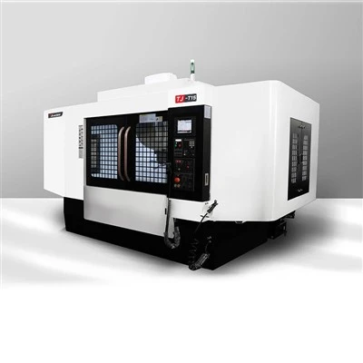
First, let’s ground this in why surface quality varies on HMCs specifically. Unlike vertical machining centers (VMCs), HMCs index workpieces horizontally, which means the tool moves along two linear axes and rotates the spindle or table around a horizontal axis. This design is ideal for high-volume, multi-sided parts—think engine blocks, aerospace brackets, or medical components that need tight tolerances across 4–5 sides. But that horizontal axis setup creates unique challenges: chip evacuation is trickier, tool runout can be harder to monitor, and the 4th-axis indexing used for multi-sided machining introduces more potential for vibration if not calibrated properly. Many shops assume their HMC’s machine tool accuracy is the only variable, but the reality is surface quality starts long before the tool touches the workpiece.
Let’s start with tool selection and condition, the single most impactful factor for surface finish on any machining center, and HMCs are no exception. I see shops reach for whatever tool is in the spindle rack when they need a finish cut, but that’s a mistake. For face milling (a common operation on HMCs, since they’re often used for flat surfaces across large workpieces), you need to match the tool’s number of inserts and corner radius to the material and desired finish. For example, when machining aluminum, a 4 or 6-flute solid carbide end mill with a polished corner radius will produce a smoother finish than a 2-flute roughing tool. When machining steel, a coated insert (like TiCN or TiAlN) reduces built-up edge (BUE)—that layer of workpiece material that sticks to the tool’s cutting edge, which leaves tiny scratches on the surface. The key here is that tool condition matters just as much as type. A worn insert, even if it’s the right grade, will leave a wavy surface pattern called chatter marks. I recommend scheduling tool inspections after every 10–15 finish cuts, and replacing inserts before their flank wear reaches 0.1mm. On HMCs, tool changeover is fast, so there’s no reason to push a tool past its limit just to save a minute.
Next, spindle speed and feed rate calibration—this is where a lot of shops cut corners because they’re working from generic feed/speed tables online. Generic tables are a starting point, but HMCs have unique spindle dynamics that demand adjusted values. For finish passes, your goal is to hit a surface speed (Vc) that minimizes BUE and chatter, while using a feed per tooth (fz) that matches your insert size. For example, when machining 6061 aluminum, a generic table might suggest 1500 SFM for roughing, but for finish milling, bumping that up to 2000–2200 SFM will reduce BUE because the tool is cutting faster, not scraping the material. For steel, 1000–1200 SFM is a good starting point, but again, adjust based on your insert coating. Feed rate is equally important: a feed per tooth that’s too high will leave a stepped pattern on the surface, while one that’s too low will cause rubbing, which generates heat and leaves a burnished, discolored finish. A general rule for finish milling on HMCs is to set feed per tooth to roughly 0.5–0.8 times the insert’s corner radius. For example, a 0.8mm corner insert would use a feed per tooth of 0.4–0.64mm. I always tell customers to test this on a scrap piece of the same material before running production parts—10 minutes of testing saves hours of rework.
Then there’s the often-overlooked factor of workholding rigidity. HMCs are designed to hold large, heavy workpieces across multiple sides, but if the vise or tombstone isn’t clamped correctly, it will flex during the cut, leading to inconsistent surface finish. I once worked with an aerospace shop that was getting chatter on every wing bracket they machined on their HMC. We inspected their workholding and found that their tombstone clamps were torqued to 20 ft-lbs, which was standard per their operator manual. But for parts over 500mm in length, that torque was too low—when the spindle made a heavy cut, the tombstone shifted 0.02mm, enough to leave chatter marks. We adjusted the clamp torque to 35 ft-lbs and added backup supports at the ends of the workpiece, and their surface roughness (Ra) dropped from 3.2 micrometers to 0.8 micrometers, which is the specification for their part. On HMCs, because workpieces are oriented horizontally during cuts, the center of gravity matters too. If you have a long part sticking out of a vise, add a steady rest or a support pin to eliminate overhang flex. Even a 0.01mm flex during a finish pass will ruin a surface that’s meant to be smooth.
Chip evacuation and cutting fluid management are next, and these are especially critical for HMCs. Because HMCs index workpieces horizontally, chips have to fall away from the cutting zone instead of being pushed straight down like on a VMC. If chips get caught between the tool and workpiece, they’ll scratch the fresh surface every time the tool makes a pass. On HMCs, I recommend using high-pressure, high-flow cutting fluid (70–100 PSI, 10–20 liters per minute) targeted directly at the cutting zone. This doesn’t just cool the tool—it blasts chips away before they can cause damage. Also, make sure your cutting fluid is filtered regularly; chips and debris in the fluid will get carried back to the workpiece, leaving small indentations on the surface. For finish cuts, I suggest using a semi-synthetic cutting fluid with good lubricity, instead of a straight coolant. The lubricity reduces friction between the tool and workpiece, which lowers heat and prevents BUE. I’ve seen shops switch from water-based coolant to semi-synthetic and see Ra values drop by 50% in some cases, just because the finish passes were cleaner.
Vibration control is another big one for HMCs, and it’s often confused with rigidity. Vibration comes from multiple sources: unbalanced tool holders, worn spindle bearings, or even the floor the HMC is sitting on. Unbalanced tool holders are a common culprit—when a holder has a worn balance or is not properly seated in the spindle, it vibrates at high speeds, creating a wavy surface pattern. I recommend investing in a tool balancing machine and balancing all finish tool holders to G2.5 at their operating speed (for most HMCs, that’s 10,000–15,000 RPM). Worn spindle bearings are harder to catch—signs of this are noise from the spindle and inconsistent surface finish. If you’re noticing random chatter marks on parts, even after changing tools and workholding, have a technician check spindle play. For new HMC owners, make sure the machine is installed on a properly leveled, reinforced floor. Shop floors can settle over time, and even a small tilt in the HMC will cause uneven tool movement, leading to poor surface quality. A quick level check of the table and spindle will catch this early.
Programming adjustments are the final piece, and they’re something even experienced CNC operators overlook. On HMCs, 4th-axis indexing (rotating the table to machine the other sides of a part) is a common source of surface variation. If you program the index to happen mid-cut, you’ll have a visible seam at the edge of the two surfaces. Instead, program the index to occur at a safe position, like a lead-in or lead-out pass, and make sure the table has fully stopped and locked before resuming the cut. Another programming tip is to use climb milling instead of conventional milling for finish passes. Climb milling is when the tool rotates in the same direction as the feed, which reduces friction and BUE, while conventional milling scrapes the material, generates more heat, and leaves a rougher surface. Most modern CNC controllers make it easy to toggle between the two, so this is a simple switch with big results. Also, add a small “finish allowance” to your program—usually 0.1–0.2mm, depending on the tool size. This gives the tool a small amount of material to remove in the final pass, so it’s not cutting through the rough tool marks left by the semi-finish pass. Skipping this allowance will leave inconsistent surface finish across the part.
I’ve seen all these strategies work in real shop environments, not just lab tests. Last year, a medical parts manufacturer reached out to me because their HMC was producing surgical instrument parts that were failing surface quality inspections. They were getting 1.6 micrometer Ra parts, but their specification required 0.8, and they were reworking 15% of parts, costing them thousands in scrap. We walked through their process together: their tool selection was wrong (they were using 2-flute tools for finish passes), their workholding clamps were under-torqued, and their cutting fluid was 6 months old and full of metal chips. We helped them swap to 4-flute tools with polished corners, adjusted the clamp torque and added supports, and replaced their cutting fluid. Within two weeks, their rework rate dropped to less than 2%, and their surface finish was consistently meeting the 0.8 Ra specification. That’s the real value of these strategies—they’re not theoretical, they deliver tangible results for production shops.

At the end of the day, improving surface quality on HMCs isn’t about buying a more expensive machine (though investing in a reliable HMC is a long-term win), it’s about optimizing every small variable in the process. Tool selection, feed and speed, workholding, chip evacuation, vibration, and programming all work together to create a smooth, consistent surface. If you’re struggling with surface quality on your horizontal machining center, these steps will help you identify where the bottleneck is. For more tailored advice or to learn how modern HMC designs integrate features that make these strategies easier to implement, feel free to reach out to our team for a no-obligation consultation about your machining operations.
Horizontal Machining Centers References
- Metal Cutting Principles, 2nd Edition, M.C. Shaw, Oxford University Press, 2005.
- Handbook of CNC Machining: Processes and Practices, Society of Manufacturing Engineers, 2018.
- Surface Finish in Milling Operations, Technical Report No. 12-007, National Institute of Standards and Technology, 2012.
- Machining Dynamics: Vibration and Stability, S. Smith and J. Tlusty, Wiley, 1999.
- Horizontal Machining Center Best Practices, Shop Floor Process Improvement Guide, Manufacturing Engineering Publications, 2021.
Guangdong Taiji Intelligent Equipment Co., Ltd.
With abundant experience, we are one of the most professional horizontal machining centers manufacturers and suppliers in China. Please feel free to buy cheap horizontal machining centers for sale here from our factory. For price consultation, contact us.
Address: Room 107, Building 15, No. 911 Jian’an Road, Chang’an Town, Dongguan City, Guangdong Province
E-mail: sale@gdtaijicnc.com
WebSite: https://www.gdtaijicnc.com/
